Posts

Showing posts from May, 2020

added to the piLagTester: test images generator to check for scaling and cliping

Of significant interest to retro gaming enthusiasts is how the display upscales low resolution input (such as 640p) to the native resolution of the display. Somewhat shockingly I've even found that some panels will scale/clip native resolution input too!!

To that end I've written some simple test image generating programs for my piLagTester program (and upcoming piLagTesterPro). Obviously this has little to do with display lag, but it's a sensible place to stash them given that they also run on a Raspberry pi (chosen for maximal physical portability) and relate to display characterization.

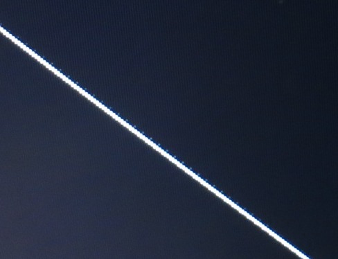
The first is lines, which just draws a set of 45 degree lines on the screen, starting at the upper left corner. This gives an easy way to see if the upscaling is picture perfect or not.

Here are two examples of 45 degree lines that aren't clean (none of this is camera artifacts).


The nice thing is this is generated pixel perfect on demand for the current resolution, so you can do tv480i; lines at the command prompt to test that resolution, or tv1080p; lines, etc. (the semicolon allows two commands on one line, you could substitute for ;)

The other test generator is called dots. By default it produces a checkerboard where each check is 1 pixel. On most modern screens this is going to look gray. The question is, does it look uniform gray, or does the gray vary vertically or horizontally, indicating sampling issues in the upscaler. I literally can't take a photo of this, because it's a camera's worst nightmare.

The program has a bonus option that lets you set the check size which can be handy, sometimes the upscaling issues only appear at 2 or 3 pixel sized checks. And if you use a check-size of 20 or more, it doubles as a clipping tester, which I can show you, though it too is hard to photograph. Below is an example with 20 pixel wide checks:


In this photo you can see that first check that's fully visible starts 40 pixels from the left edge. Checks are spaced every 20 pixels, so that means that about (can you guess?)........... 20 pixels are cut off here. Note: the same resolution changing options work here as with lines (ie tv720p;check 20)

If you want to give them a try on your Raspberry Pi download them here.


The *other* source of input lag

While my main focus has been measuring input lag purely as a function of the tv/display, it's interesting to note that the input device (aka gamepad) can make a difference too. More than just a couple MS, too.

teyah.net/ looked at a bunch of 3rd party fighting game controllers for the PS4/PS3 and the delta between the best and worst was a whopping 18ms. Which is to say that simultaneously push a button on the fastest input device and the slowest would result in the console detecting input 18ms later on the slowest. Happily, the standard ps4 controller was only 2ms behind the fastest, at least when only one was being used (multiple controllers caused radio interference).

Note that this doesn't tell us total lag - presumably the fastest device still gets polled every few MS. But you don't buy absolutes so knowing the relative performance is good enough!

Another person measured total lag for PS4 and other game systems with different controllers, from button press to measurable change in the component video signal (ie before display lag contributes anything). The values ranged from 45ms to 100ms. Certainly enough to swamp display lag in many cases. Side note: this is really interesting work but presented really poorly. Perhaps there's a proper write up somewhere other than the the only forum post I could find about it?

Most impressively of all this person, who built their own USB host (an arduino)  that could "push" (electrically) the buttons on a device, and then measure the time to get a different controller state back over the USB cable. And, they did an excellent write up and graphical presentation of their results too. It's so nicely presented I won't bother to summarize the results other than to say again the range of lags were 2 to 23ms.


Raspberry Pi Zero as a high-speed datalogger

How well suited is the RPI zero as a high speed data logger? Depends on the definition "high speed", but I was able to sample a 16 bit number about 10 times per millisecond over the ic2 bus, and you could probably do better.

(1) The Pi can keep up!
I'm using a relatively bog-standard distribution of Linux on a raspberry pi zero, not RT linux or anything like that. My sampling device is the TI ADS1015, which only provides 3300 unique samples per second at 12 bits. That's  3.3 samples per millisecond, so the pi is overkill for keeping up with it.

Now, that's not to say it's always hitting every 0.1ms mark. (1) is a representative graph of the time between samples taken over the IC2 bus in a tight loop(1*) without any other significant activity going on (networking is active, but not pushing anything in or out) for 300ms.  Killing the network hardware and stack does improve things, maybe 25% more samples? I've not measured carefully).
This is running as root, with nice(-18); during capture (and 0 otherwise to unstarve the kernel/whatever). As you can clearly see there are some regular glitches in the capture, apparently every 120ms, which is an odd frequency, I don't know what that is). But in my use case, 5 samples per MS still beats the ADS1015. Occasionally I do actually drop a single ADS1015 sample on the floor, but it's rare, and in my use case I can just repeat the measurements again automatically if the glitch occurs in an important part of the data. 

To underscore that point see (2), the histogram of the same data showing the count of samples taken more than 0.1ms appart (everything near 0.1 ms and below is waaaaay off the top of the chart).  Data only get lost on average when the delta is > 0.3ms, which only happened 5 times, out of ~3500 samples. 

(2) very few dropped samples
I'm satisfied, especially given that this $5 device has a HDMI port, which is critical for my use case. 


notes:
(1*)

int readval() {
  if (read(fd, readBuf, 2) != 2)  // read conversion register
{ perror("Read conversion"); exit(-1); }
 return readBuf[0] << 8 | readBuf[1]; // could also multiply by 256 then add readBuf[1]
 }

for(...) {
 on_buff[i]=readval();
 on_times[i] =  (microsec();- start); 
}

Using the piLagTester to measure display input lag: step by step

The piLagTester a 100% software solution for measuring input lag on the raspberry pi zero. If you have already installed the piLagTester to your raspberry pi then you are ready to make measurements.

0) Camera orientation. First, you need to make sure your camera is capturing the output of the Pi's LED at the same time it's capturing the target bar. This depends on the orientation of your camera. The reason is that camera's don't actually record all pixels at the same moment in time. Instead they scan from one side of the sensor to the other. How long this takes is unknown, but definitely influenced my results. What we want is to set up the camera so that it's scanning from left to right (or right to left). Thus, the vertical extent of the target bar will be determined entirely by what the display has shown, and not at all by how far DOWN the screen the camera has scanned.

You can determine this by setting your camera to the highest frame rate (or set it to take a very short exposure photo) and record your display with a solid white image. The backlight will flicker on and off much faster than the refresh rate of the screen, changing how bright that "white" image is. If the screen varies in brightness like the picture at left then you have found the proper orientation of your camera: Every vertical line of pixels were captured at the same moment of time; but moving left to right in the image shows different times, including a period where the backlight was off (the dark region). What you don't want to see: the samge image, but the dark/bright regions running left to right.

1) to start the program you type inputLagLED at the prompt after logging in as root. If you can't login as root, then you can type sudo bash to get a root prompt. The photo at right shows what to expect. The leftmost vertical bar is the "target". It has not finished drawing in this frame, which is why it is dark at the bottom. To the right of this is a stair step of intensities from black to white; these are a visual aid for measuring how far down the screen the bar extends and also camera exposure. The rightmost vertical bar could be confused for the target but actually only turns off the same frame the target turns on. This is designed to keep any auto dimming or dynamic contrast enhancement from confusing the results, and also helps your camera have the proper exposure. Finally, just off the edge of the photo at right is a set of numbers. These tell you the current frame of animation - the target turns on at frame 0. This helps you fast forward thru your video to get to the interesting frames.

2) Pi placement. Now that you have the camera oriented so that each vertical line of pixels are captured at the same moment, you need to place the pi so that the LED is captured at the same moment the bar is photographed. That means placing it below the target bar (ie, at the lower left edge of the display). The height of the Pi doesn't matter, just the left-right position. See photo at right.

2) Record! Once you have everything lined up properly just start taking a movie at the maximum frame rate of your camera (recall that 60hz is good enough but 240hz or higher makes the math much simpler). You'll want to record about 10 appearances of the white bar before stopping (Esc), just to be sure you have enough data. 

3) Analyze. As discussed in the general overview, the simplest way to measure lag is to find the first frame of video where the LED goes from off to on - any amount of LED increase in illumination counts. Then from there count the number of frames until the target bar appears. This, times the length of each frame of video (1/FPS) gives the lag.  An example: below are 3 frames of video, the first at left being the first frame of video where the LED turns on. We don't count that one. Then we count the next (middle frame). Then we count the frame where the target becomes visible. That's two frames times the refresh rate of the camera (NOT the monitor). 


Note: why don't we count it as 3 frames? Because we don't know when the LED turned on, so we assume halfway thru the captured frame of video. And we don't bother to estimate when the target bar started to appear in the last frame, so again we assume halfway. so you could say we count 0.5 + 1 + 0.5=2. But it's easier to just count the last frame as 1 and skip the halfsies. 

Good software for this does not appear to be available for android. But on the desktop there are lots of movie editing apps which allow you to step ahead and back by single frames. I use shotcut (Win/Mac/Lin).

5) Measuring input lag for interlaced content, or different resolutions. Retro gamers will be particularly interested in input lag for 480i and 480p signals. The Pi can produce such signals over HDMI, which is probably the same as sending it over analog cables (both are realtime scanout protocols, at least).  I've included several mode settings scripts:

tv1080p  
tv480i  
tv480p 
tv720p  
tvnative

The last one can be useful for checking the display's native resolution in a hurry. Also, the pi defaults to 1080p in some cases where the display can't handle it, so you could always type tvnative blind after logging in as root.

6) Supporting burst high-speed cameras. You can change the length of time the target bar is on the screen, to, for instance, capture several cycles of bar presentation on a high speed camera that only captures in short bursts. Type inputLagLED 8 to run it much faster, though this isn't really recommended unless your monitor has very little lag and super fast response time. The default is 20, the not so safe min is 4. A whole cycle of target and non target bars takes 2x the number you provide, divided by the refresh rate. 

7) supporting slow cameras. Just to remind you, a slow camera doesn't stop you from using this tool, as long as it can record at 60 hz and you can do simple math.


Download and install piLagTester for the Raspberry Pi Zero

The piLagTester is a simple DIY device for measuring input lag, using parts that cost $5-10. It's easy to set up since it uses a Raspberry Pi Zero board with zero hardware modifications or any additional parts beyond the normal pi0 accessories. Probably all pi3 and lower will work, but I've not tested that. The Pi4  is definitely not supported, however, due to some dumb choices they made about direct access to the onboard LED.

In order to guarantee the timing is correct I'm providing a custom OS image with the software included and ready to go with no additional configuration. The OS image happens to be the same one as used by the piLagTesterPRO, so that I don't have to maintain multiple OS images and all the required storage.

The direct link is:  email me for link

To install this to a 4gb (or larger) micro SD card you'll need to unzip it and then to use an app like win32diskimager, rufus, or equivalent. The raspbian official download page goes into the details so I'll skip them here.

Once written to SD card you can put it in your pi0 and turn it on.

No password required (but it's root/t if you need to know). Consider this encouragement to not have it on the network, since you get tighter timing that way.

All the software lives in /x, which happens to be in the path too. The main executable is inputLagLED

As it's part of the piLagTesterPRO distribution (an advanced version that requires custom hardware) there's other stuff in the /x folder that's not of much use to you, but in particular all the scripts that start with tv are useful for setting the resolution that you will test:

/root #ls /x/tv*
/x/tv1080i  /x/tv240p  /x/tv480p  /x/tvcea  /x/tvnative
/x/tv1080p  /x/tv480i  /x/tv720p  /x/tvdmt


That's it. Next up: time to use it!

Accessing Win10 file shares from WinXP

Unlike most people I won't say "just stop using WinXP". WinXP is great. Here I was trying to run it in a VMware 15 virtual machine hosted under Win10. And I couldn't get XP to browse or map shares using net use h: \\m5\h$

instead I got error 64

Here's the powershell command that seems to be critical to making it work:

Enable-WindowsOptionalFeature -Online -FeatureName smb1protocol

Warning! this will cause your computer to reboot.

This is from https://docs.microsoft.com/en-us/windows-server/storage/file-server/troubleshoot/detect-enable-and-disable-smbv1-v2-v3 which also helpfully inlcudes a command to check if smb1 was enabled (it wasn't, even though I went thru the optional features GUI to install it, and rebooted as required).

There's a lot of other suggestions made out there. Some that notably don't seem to be required:

"Turn off password protected sharing"

(from https://tinyapps.org/blog/201805170700_winxp_to_win10_folder_share.html). I haven't tried to see if any of the other suggestions are wrong - ie I tried them all before hitting on the magic powershell command above.

Input Lag measurement using a slow high-speed camera: achieving millisecond accuracy with piLagTester

The piLagTester is a cheap ($5) DIY input lag tester based on a Raspberry Pi Zero using any camera capable of recording video at 60FPS or higher. This post details how to get 1-2ms resolution even if you only have a 60FPS camera. If you are not familiar with the piLagTester read the overview first.


The basic procedure is to load the video into an editor that lets you advance frame by frame. I use shotcut, but there are many. Sadly, none that I have found for android that let you advance and backup by single frames.

Search thru the video until you find the frame where the Pi LED first lights up. This is the moment when the frame showing the target white bar has been fully sent over HDMI to the monitor. Now we count frames until the target takes to show up. Advance frame by frame until the white probe first appears at the top of the screen (it's the tall white/gray bar in the 3rd frame under under the "word" BRAVIA). In this example that's 2 frames of delay. That times the length of the camera frame (1/FPS =16ms) tells you the lag (32ms), with an average error of 1 frame length. If the camera is very fast this is plenty good enough, for instance a Samsung S9 running at 960fps will only be off by about 1 ms.

With a slower camera 1 frame of error might be intolerable. But it's possible to do almost as well as a high speed camera using some math. If you have a 240fps camera just skip the following unless you like math.

Let's try the same example with a 60fps camera (60fps=60hz=16ms between frames). We extend the same counting method, but now with partial frames. The first frame where the LED lights up counts for 1/2 a frame because we don't know if it lit up at the beginning or end of when the frame was captured. So we assume halfway.

Each additional frame with no white bar counts for 1 full frame, as does the frame where the white bar appears. But that last frame is going to be an overestimate because we know the display started drawing before the frame was captured. We can estimate how much by measuring how far down the screen the bar reaches. The further down the screen, the further back in time. In this case it's about 90% to the bottom, so we can subtract 90% of the length a monitor refresh cycle, giving the following calculation: (0.5 +1 + 1) x 16 - (0.9 x 16). Here the refresh rate and the camera are both 60hz, so we can combine the addition before multiplying, giving (0.5 + 1 + 0.1) * 16 = 25.6ms. This compares quite favorably to oscilloscope based measures of this monitor's lag time, between 23ms and 24ms.

Confused? Let's consider another example also with a 60fps camera and a 60hz monitor.


At the top we have a representation of the frames captured by the camera. The timeline shows the moment in time those frames are captured (we'll assume instantly, or close enough if you orient your camera properly).

On the first frame the LED is off 10ms after the previous frame the LED turns on. Since we have no way to measure this, we just assume it's on half the frame, so we count 0.5 frames. Then we have 1 full frame where the LED is on and the target does not appear. On the next frame, at 48ms, the target bar is seen in the camera's frame, but only 25% of it. We include the full final frame in our count, and multiply the count times the camera's frame length: (0.5 + 1 + 1)x16ms = 40ms. This is of course an overestimate. To correct we subtract the amount of time the target was visible when the final frame was captured. Here that's 25% of the time it takes the monitor to draw from the top of the screen to the bottom, aka the refresh rate. So we would subtract 0.25x16ms, giving the final answer of 40ms-4ms=36ms.

Here are some examples worked out:

75hz display, 120fps camera, LED on 2 frames and then on the 3rd 30% of the target appears:
(0.5 + 1 +  1) x 1/120   - 0.3 x 1/75

120hz display, 240fps camera, LED on 3 frames and then on the 4th 80% of the target appears:
(0.5 + 1 + 1 + 1) x 1/240   - 0.8 x 1/120

Using this method the error should be relatively low, on average no more than half the framerate of the camera. This is because we don't actually know when the LED turned on within the frame and have to guess halfway. A 60hz camera would give 8ms of error, and a 120hz camera would give just 4ms. But that's on average, the worst case is certainly possible (1 full frame off). The solution is to take a longer video and record 5-8 presentations of the target bar and then average the estimates. This seems to give a resolution of 1-2ms.

Why: long answer. Because of the magic of averages the final estimate can actually be more precise than the average error, assuming the error is random. Imagine that we measured 16 times, and by luck measured the spacing between the target onset and the camera frame capture evenly in 1 ms increments. It's easy to see that our estimate that LED turned on exactly halfway between captured frames would be too high 8 times and too low 8 times. But on average it would be exactly right. Of course we don't have to make 16 measurements, just enough that the average error is near zero. 5-8 seems to be about the right number.

Why: short answer. Just like any scientist you need to take multiple measurements because no one measurement is going to be perfect. What, you didn't realize you were a scientist? That's right, owning a piLagTester is all it takes, skip grad school and jump straight to the fame and fortune that a PhD confirs. And, since the piLagTester is a DIY project, grant yourself an honorary BS in engineering while you are at it (degree granting is one of the privileges of having a PhD).


A $5 TV Input Lag tester using a Raspberry Pi Zero

High speed monitors are all the rage now, with quoted response times of 1-4ms. But does that mean that 1-4ms after you make an input (say, jump) you will see that on your screen? No. Often a much bigger issue is Input lag. This is the delay between your computer / game console sending a video frame to your display and your display starting to actually show it, and it ranges from 4ms to 80ms.

The problem with measuring input lag is that you can't, at least with everyday hardware. The solution for hardware review sites is to purchase dedicated lag testers such as the leo bodnar tester,  timesleuth (both ~$100), or the pi lag tester pro ($40) or use homegrown methods utilizing an oscilloscope ("free" if you already own a $400+ oscilloscope and perhaps a $50k+ engineering degree).

Here I introduce a $5 solution (or, "free" if you own the required equipment). What's required:

  1. A Raspberry Pi Zero ($5 + S&H from several sources). This single board computer runs Linux and out-specs SGIs I played with in the early 90s. Other more expensive Pi's might work but I haven't tested them and I'd be hesitant to guarantee the timing. Furthermore, the lack of WIFI support is actually positive, since it reduces timing noise.
  2. A (barely) high speed camera: 60fps is fast enough, but higher does reduce the error rate. 120hz-240hz phone cameras are pretty common, such the Samsung S7 or any more recent variant, or any recent iphone.  Feel free to add to this list in the comment section below. To be fair, for a few people this will increase the cost significantly beyond $5. But, you can use that nice camera for other things, unlike dedicated lag testers.
  3. A mini HDMI to full HDMI adapter.
  4. A MicroUSB OTG adapter (often sold for phones)
  5. A 4GB MicroSD card (or larger).
  6. A moderately decent MicroUSB power supply (1A is enough, more is fine).
To be fair I'm assuming that you have #2-6, which is probably not entirely fair. So bump the price up another $5 for parts #3-5 if ordered from ebay (etc) as part of a raspberry pi accessory kit. #6 can come from your phone. Or go wireless and use a powerbank for portability.

The setup is fairly simple and requires no soldering or other electrical engineering experience. The basic approach is as follows: The Pi is connected to your TV, and a free program I wrote sends a white bar to the screen and simultaneously turns on the built-in LED on the Pi. You record all this with your camera and measure the number of frames between the LED lighting up and the white bar appearing on the screen. An example is shown below.


Here we have 3 frames of video - for simplicity the preceding frame when the LED off is left out. Unfortunately the built-in LED is very small; just 4 or 6 pixels here, but the visibility is better when you can see it change state. Count the number of frames where the LED is on before the white bar appears on the leftmost side of the screen (under the "word" BRAVIA). In this case that's 2 frames. That times the length of the camera frame (16ms) tells you the lag (32ms), with an average error of 1 frame length. If the camera is very fast this is plenty good enough, for instance a Samsung S9 running at 840fps will only be off by about 1.2 ms.

What if you only have a 60fps camera? You can do almost as well with a little more math, described in detail elsewhere, but here's the gist: the frame where the LED lights up counts for half, and you measure how far down the screen the white bar extends down the final frame to calculate its contribution. In this example that's (0.5 + 1 + 0.1) * 16 = 25.6ms, which compares quite favorably to 23ms-24ms measured with an oscilloscope, but in reality you'll have to average over several measurements to get a good estimate.

My hope is that this rather cheap lag tester will be popular enough to greatly increase the data on input lag for many TV/monitors. Not just the recent, high end gaming displays for which this tends to be published, but also more mainstream displays and even older equipment available quite cheaply on the used market. Please contact me if you are interested in getting one of these set up and are having issues after reading the list below. My eventual hope is to set up a database like I have for piLagTesterPRO of the results collected using this technique, and sourced from community contributions.

Related posts:

  1. how to setup the Raspberry Pi Zero, and a download link for the software needed.
  2. set by step procedure for setting up a camera (of any speed), running the pi software, and then counting frames on your pc.
  3. more detailed steps for using this with cameras that only run at 120hz or slower, as well as a deeper discussion of the math behind why that works
  4. bonus: upscaling test generator
  5. a rambling discussion of the ins and outs of measuring input lag using any hardware, and what it makes sense to measure AND report (does anybody really want to read the last one? Maybe I should stop there).
Meanwhile, if this strikes you as all too much work, or if you really want to be able to measure top/middle/and bottom of the screen lag, I have another project that won't be as cheap but will be infinitely easier and also more powerful. I call it the piLagTesterPro. With it's own sensor it can measure input lag directly and produce pretty plots in real time + log data for later analysis. You just provide the Raspberry Pi.


Email me

Name

Email *

Message *