A $5 TV Input Lag tester using a Raspberry Pi Zero
High speed monitors are all the rage now, with quoted response times of 1-4ms. But does that mean that 1-4ms after you make an input (say, jump) you will see that on your screen? No. Often a much bigger issue is Input lag. This is the delay between your computer / game console sending a video frame to your display and your display starting to actually show it, and it ranges from 4ms to 80ms.
The problem with measuring input lag is that you can't, at least with everyday hardware. The solution for hardware review sites is to purchase dedicated lag testers such as the leo bodnar tester, timesleuth (both ~$100), or the pi lag tester pro ($40) or use homegrown methods utilizing an oscilloscope ("free" if you already own a $400+ oscilloscope and perhaps a $50k+ engineering degree).
Here I introduce a $5 solution (or, "free" if you own the required equipment). What's required:
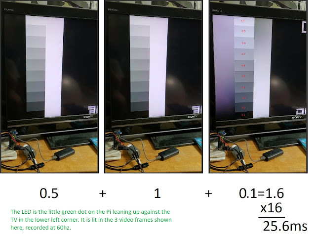
Here we have 3 frames of video - for simplicity the preceding frame when the LED off is left out. Unfortunately the built-in LED is very small; just 4 or 6 pixels here, but the visibility is better when you can see it change state. Count the number of frames where the LED is on before the white bar appears on the leftmost side of the screen (under the "word" BRAVIA). In this case that's 2 frames. That times the length of the camera frame (16ms) tells you the lag (32ms), with an average error of 1 frame length. If the camera is very fast this is plenty good enough, for instance a Samsung S9 running at 840fps will only be off by about 1.2 ms.
What if you only have a 60fps camera? You can do almost as well with a little more math, described in detail elsewhere, but here's the gist: the frame where the LED lights up counts for half, and you measure how far down the screen the white bar extends down the final frame to calculate its contribution. In this example that's (0.5 + 1 + 0.1) * 16 = 25.6ms, which compares quite favorably to 23ms-24ms measured with an oscilloscope, but in reality you'll have to average over several measurements to get a good estimate.
My hope is that this rather cheap lag tester will be popular enough to greatly increase the data on input lag for many TV/monitors. Not just the recent, high end gaming displays for which this tends to be published, but also more mainstream displays and even older equipment available quite cheaply on the used market. Please contact me if you are interested in getting one of these set up and are having issues after reading the list below. My eventual hope is to set up a database like I have for piLagTesterPRO of the results collected using this technique, and sourced from community contributions.
Related posts:
The problem with measuring input lag is that you can't, at least with everyday hardware. The solution for hardware review sites is to purchase dedicated lag testers such as the leo bodnar tester, timesleuth (both ~$100), or the pi lag tester pro ($40) or use homegrown methods utilizing an oscilloscope ("free" if you already own a $400+ oscilloscope and perhaps a $50k+ engineering degree).
Here I introduce a $5 solution (or, "free" if you own the required equipment). What's required:
- A Raspberry Pi Zero ($5 + S&H from several sources). This single board computer runs Linux and out-specs SGIs I played with in the early 90s. Other more expensive Pi's might work but I haven't tested them and I'd be hesitant to guarantee the timing. Furthermore, the lack of WIFI support is actually positive, since it reduces timing noise.
- A (barely) high speed camera: 60fps is fast enough, but higher does reduce the error rate. 120hz-240hz phone cameras are pretty common, such the Samsung S7 or any more recent variant, or any recent iphone. Feel free to add to this list in the comment section below. To be fair, for a few people this will increase the cost significantly beyond $5. But, you can use that nice camera for other things, unlike dedicated lag testers.
- A mini HDMI to full HDMI adapter.
- A MicroUSB OTG adapter (often sold for phones)
- A 4GB MicroSD card (or larger).
- A moderately decent MicroUSB power supply (1A is enough, more is fine).
To be fair I'm assuming that you have #2-6, which is probably not entirely fair. So bump the price up another $5 for parts #3-5 if ordered from ebay (etc) as part of a raspberry pi accessory kit. #6 can come from your phone. Or go wireless and use a powerbank for portability.
The setup is fairly simple and requires no soldering or other electrical engineering experience. The basic approach is as follows: The Pi is connected to your TV, and a free program I wrote sends a white bar to the screen and simultaneously turns on the built-in LED on the Pi. You record all this with your camera and measure the number of frames between the LED lighting up and the white bar appearing on the screen. An example is shown below.

Here we have 3 frames of video - for simplicity the preceding frame when the LED off is left out. Unfortunately the built-in LED is very small; just 4 or 6 pixels here, but the visibility is better when you can see it change state. Count the number of frames where the LED is on before the white bar appears on the leftmost side of the screen (under the "word" BRAVIA). In this case that's 2 frames. That times the length of the camera frame (16ms) tells you the lag (32ms), with an average error of 1 frame length. If the camera is very fast this is plenty good enough, for instance a Samsung S9 running at 840fps will only be off by about 1.2 ms.
What if you only have a 60fps camera? You can do almost as well with a little more math, described in detail elsewhere, but here's the gist: the frame where the LED lights up counts for half, and you measure how far down the screen the white bar extends down the final frame to calculate its contribution. In this example that's (0.5 + 1 + 0.1) * 16 = 25.6ms, which compares quite favorably to 23ms-24ms measured with an oscilloscope, but in reality you'll have to average over several measurements to get a good estimate.
My hope is that this rather cheap lag tester will be popular enough to greatly increase the data on input lag for many TV/monitors. Not just the recent, high end gaming displays for which this tends to be published, but also more mainstream displays and even older equipment available quite cheaply on the used market. Please contact me if you are interested in getting one of these set up and are having issues after reading the list below. My eventual hope is to set up a database like I have for piLagTesterPRO of the results collected using this technique, and sourced from community contributions.
Related posts:
- how to setup the Raspberry Pi Zero, and a download link for the software needed.
- set by step procedure for setting up a camera (of any speed), running the pi software, and then counting frames on your pc.
- more detailed steps for using this with cameras that only run at 120hz or slower, as well as a deeper discussion of the math behind why that works
- bonus: upscaling test generator
- a rambling discussion of the ins and outs of measuring input lag using any hardware, and what it makes sense to measure AND report (does anybody really want to read the last one? Maybe I should stop there).
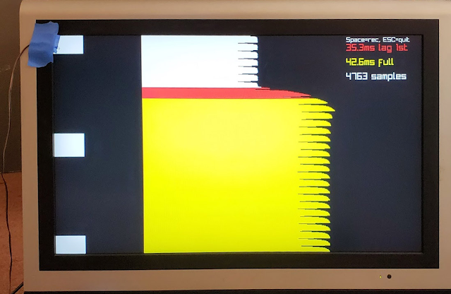
Meanwhile, if this strikes you as all too much work, or if you really want to be able to measure top/middle/and bottom of the screen lag, I have another project that won't be as cheap but will be infinitely easier and also more powerful. I call it the piLagTesterPro. With it's own sensor it can measure input lag directly and produce pretty plots in real time + log data for later analysis. You just provide the Raspberry Pi.
Comments
Also tried Pi4 but didn't see an InputLagLED executable.
Thankya!
I only tested on a pi0, though my understanding at the time was that the LED should use the same GPIO pin on later models. But maybe it does not. If you can determine what pin number to use I can upload a new image that should work on the pi3, or make it user specifiable. I don't have a 3 to test on.
I suppose making it user specifiable also has the advantage that you could wire in a LED on a pi4 that could be controlled with MS precision...
It looks like the pinout is the same for all Pis that use 40-pin headers, but definitely fact-check me that.
the pi4 is still a no-go because of the different graphics stack, independent of LED blinking issues.
Is there a GPIO pin pair that *should* work right now? I haven't tried that yet, but you are correct that the Zero and 3 series share GPIO pinouts. Thanks in advance for any help!
same issue with 3b+, they changed the GPIO port for the LEDs (note how the title of the post is "pi zero". Turns out that's really true, though at the time I didn't know how specific it was to that model. What I can do since there's some interest is compile a version where the port number is user-settable, at which point everything sub pi4 will be supported.